描述

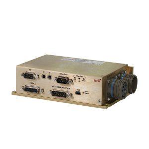
Eagle HV (High Voltage) Digital Servo Drive
The Eagle HV series of digital servo drives are highly resilient and designed to deliver the highest density of power and intelligence. The Eagle HV delivers up to 65 kW of continuous power in a compact package.
The digital drives are based on Elmo’s advanced SimplIQ motion control technology. They operate from a DC power source in current, velocity, position and advanced position modes, in conjunction with a permanent-magnet synchronous brushless motor, DC brush motor, linear motor or voice coil. They are designed for use with any type of sinusoidal and trapezoidal commutation, with vector control. The Eagle HV can operate as a stand-alone device or as part of a multi-axis system in a distributed configuration on a real-time network.
The drives are easily set up and tuned using Elmo’s Composer software tools. This Windows-based application enables users to quickly and simply configure the servo drive for optimal use with their motor. The Eagle HV, as part of the ExtrIQ product line, is fully programmable with Elmo’s Composer motion control language.
Power to the drives is provided by a DC power source (not included with the Eagle HV).
Mating Power Supply Elephant.
Eagle HV Highlights:
- Ready to use in extreme conditions
- SimplIQ core motion control technology
- Ultra-high qualitative power density
- Panel mounting
- Top efficiency
- Supports a wide variety of feedbacks
- Vector control sinusoidal commutation
- Advanced filtering and velocity gain scheduling for enhanced dynamic performance
Power Ratings for 400 V Models
Feature | Units | 50/400 | R100/400 |
|---|---|---|---|
Minimum supply voltage | VDC | For S type*: 50 |
|
Nominal supply voltage | VDC | 325 |
|
Maximum supply voltage | VDC | 400 |
|
Maximum continuous power output | kW | 16 | 33 |
Efficiency at rated power (at nominal conditions) | % | > 98 |
|
Auxiliary supply option, for S drives | VDC | 18 to 30 |
|
Auxiliary power supply (external option) | VA | 7 |
|
Continuous current limit (Ic) amplitude of | A | 50 | 100 |
Sinusoidal continuous RMS current limit (Ic) | A | 35 | 71 |
Peak current limit | A | 100 | No peak |
Weight | kg (oz) | 1.623 kg (57.25 oz) |
|
Dimensions | mm (in) | 180 x 142 x 75.2 (7.08" x 5.59" x 2.96") |
|
Digital in/Digital out/ Analog in | 6/4/1 |
||
Mounting method | Panel / Wall Mounted |
||
Power Ratings for 700 V Models
Note: This model will not be used in new designs of the drive.
Feature | Units | 35/700 | R70/700 | R100/700 |
|---|---|---|---|---|
Minimum supply voltage | VDC | For S type*: 100 |
||
Nominal supply voltage | VDC | 560 for 400 VAC |
||
Maximum supply voltage | VDC | 700 |
||
Maximum continuous power output | kW | 20 | 40 | 57 |
Efficiency at rated power (at nominal conditions) | % | > 98 |
||
Auxiliary supply option, for S drives | VDC | 18 to 30 |
||
Auxiliary power supply (external option) | VA | 7 |
||
Continuous current limit (Ic) amplitude of | A | 35 | 70 | 100 |
Sinusoidal continuous RMS current limit (Ic) | A | 25 | 50 | 71 |
Peak current limit | A | 70 | No peak | No peak |
Weight | kg (oz) | 1.623 kg (57.25 oz) |
||
Dimensions | mm (in) | 180 x 142 x 75.2 (7.08" x 5.59" x 2.96") |
||
Digital in/Digital out/ Analog in | 6/4/1 |
|||
Mounting method | Panel / Wall Mounted |
|||
Power Ratings for 700 V Models
Feature | Units | 35/800 | R70/800 | R100/800 |
|---|---|---|---|---|
Minimum supply voltage | VDC | For S type*: 100 |
||
Nominal supply voltage | VDC | 560 for 400 VAC |
||
Maximum supply voltage | VDC | 780 |
||
Maximum continuous power output | kW | 22 | 45 | 65 |
Efficiency at rated power (at nominal conditions) | % | > 98 |
||
Auxiliary supply option, for S drives | VDC | 18 to 30 |
||
Auxiliary power supply (external option) | VA | 7 |
||
Continuous current limit (Ic) amplitude | A | 35 | 70 | 100 |
Sinusoidal continuous RMS current limit (Ic) | A | 25 | 50 | 71 |
Peak current limit | A | 70 | No peak | No peak |
Weight | kg (oz) | 1.623 kg (57.25 oz) |
||
Dimensions | mm (in) | 180 x 142 x 75.2 (7.08" x 5.59" x 2.96") |
||
Digital in/Digital out/ Analog in | 6/4/1 |
|||
Mounting method | Panel / Wall Mounted |
|||
Feature | Operation Conditions | Range |
|---|---|---|
Ambient Temperature Range | Non-operating conditions | -50 °C to +100 °C (-58 °F to 212 °F) |
Operating conditions | -40 °C to +71 °C (-40 °F to 160 °F) | |
Temperature Shock | Non-operating conditions | -40 °C to +71 °C (-40 °F to 160 °F) within 3 min. |
Altitude | Non-operating conditions | Unlimited |
Operating conditions | -400 m to 12,000 m (-1312 to 39370 feet) | |
Relative Humidity | Non-operating conditions | Up to 95% relative humidity non-condensing at 35 °C (95 °F) |
Operating conditions | Up to 95% relative humidity non-condensing at 25 °C (77 °F), up to 90% relative humidity non-condensing at 42 °C (108 °F) | |
Vibration | Operating conditions | 20 Hz to 2000 Hz, 14.6 g |
Mechanical Shock | Non-operating conditions | ±40g; Half sine, 11 msec |
Operating conditions | ±20g; Half sine, 11 msec |


